IoT Devices Lab Series 4 - Working with GPIOs
Introduction
In this lab, you will start working with external components to your Dev Board that will be managed through GPIOs.
Pre-requisites
Info
This lab guide is written form Mac OS X and Linux. If you have a Windows Machine, go and read the first part of this series to set up a Linux-based IoT Development workstation on a VM on your laptop.
The tutorial assumes you have Python3 and that you have a working environment and dev board as described in the second part of this series. If you're looking for a very basic introduction to Micropython on the ESP32, follow the third part of this series instead.
You'll also need the following materials:
- A development environment with direct USB access (your laptop) and Internet connectivity
- WiFi connectivity (user and password based authentication, certificate based authentication will not work). A mobile phone configured to share the connection via WiFi will do.
- An ESP32-based development board
- A USB-A/USB-C to micro USB data cable to connect the dev board to your computer.
- Two or three LEDs
- Two or three 330 Ohm resistors
- Assorted jumper wires
- [OPTIONAL] A potentiometer and a push button
- [OPTIONAL] A multimeter, for checking current draw during sleep mode
- Two breadboards, one of the with the power rail removed
Pinout
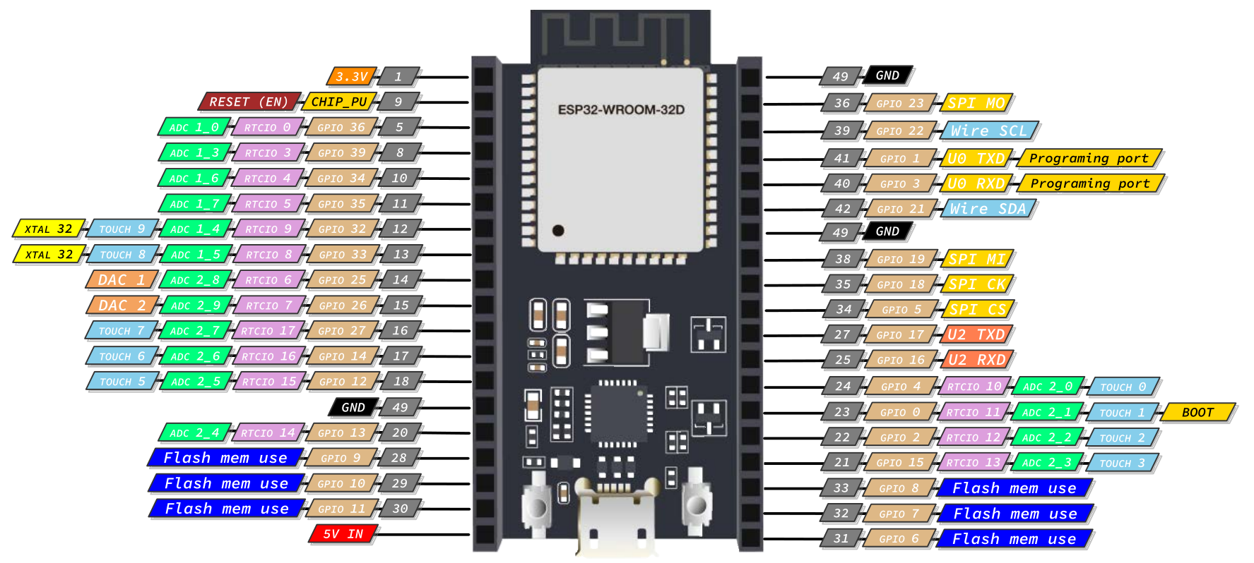
For the purpose of this lab, we'll be using a Espressif ESP32 WROOM 32D. Any ESP32 device will do although the pinout may be different. Keep that in mind when following through.
The pinout for the ESP32 WROOM 32D that we'll be referring from now on is this:
Setting up the environment
Place the ESP32 Dev Board and the breadboards as shown in the image by breaking off one of the power rails of one of the two breadboards (the other one is to be left intact):
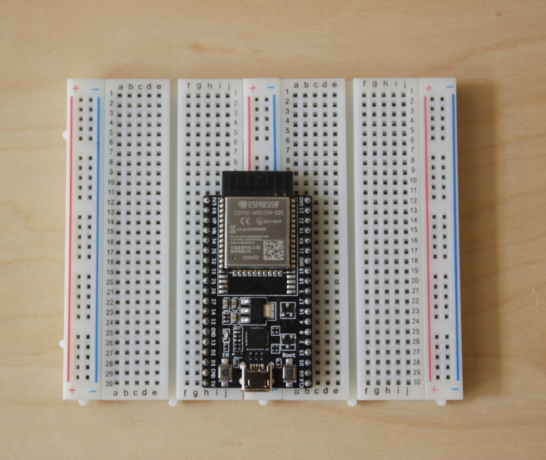
Two breadboads are needed as it is quite possible that the ESP32 Dev Board that you have is not breadboard-friendly (meaning that it's wide enough that it won't let any free holes for jumper wire connectivity). This will for sure be the case is you have one of the Dev Kits supplied by Espressif.
It is also recommended (but not required) that you connect with jumper wires both the output 3.3V (Vcc) and the GND pins to the corresponding power rails in the breadboard. If possible, use black for GND and red for Vcc so it's easy to identify. This way, you'll have easier access to GND and Vcc when connecting additional components.
Once this is done, connect the Dev Board to your PC using the USB cable and fire up your development environment (minicom + ampy, Thonny, VSCode + Pymark... pick your poison).The embedded power LED in the Dev Board should light up and your should be ready to go.
Info
This guide won't make assumptions on how you connect to the board, run code, or transfer files to it. If you want to get an initial taste of different tools available, visit the second and third part of this series.
Control GPIO output (with external LED)
First, let's understand the basics of controlling digital outputs through GPIO.
How to make the connections:
These are the connections you'll need to make for the code in this section to work:
- Connect GPIO 32 to one end of a 330 Ohm resistor
- Connect the other end of the previous 330 Ohm resistor to the positive pin of a LED (remember, LEDs have polarity)
- Connect the negative pin of the previuos LED to GPIO 49 (GND) or to the ground rail if you're using it.
Now, access a Python REPL in the device and try the following code to set up Pin 32 as a Digital output pin that we can then control:
from machine import Pin
led0 = Pin(32, Pin.OUT)
led0.value(1)
This should ligh up the LED. We can get the value of the output pin, and turn it off by doing:
print(led0.value())
led0.off()
Let's do something slightly more sofisticated by using the Micropython module time:
from machine import Pin
import time

led0 = Pin(32, Pin.OUT, value=1)

while(True):
    led0.on()
    time.sleep_ms(500)
    led0.off()
    time.sleep_ms(500)
Now the led will flash every 0.5 seconds unless you stop the program or reset the device.
Using a different pin
Try the previous simple code to ligh up a led using Pin 5 instead of Pin 32:
from machine import Pin
led0 = Pin(32, Pin.OUT, value=0)
led0.on()
led0.off()
Now reset the board and see if there's any light in the LED. If there is, why is that?
Using timers
Let's do something more interesting with the previous Digital output, learning about another Micropython module in the process: the timer module.
How to make the connections:
These are the connections you'll need to make for the code in this section to work:
- Connect GPIO 16 to one end of a 330 Ohm resistor
- Connect the other end of the previous 330 Ohm resistor to the positive pin of a LED (remember, LEDs have polarity)
- Connect the negative pin of the previuos LED to GPIO 49 (GND) or to the ground rail if you're using it.
- Connect GPIO 17 to one end of a 330 Ohm resistor
- Connect the other end of the previous 330 Ohm resistor to the positive pin of a LED (remember, LEDs have polarity)
- Connect the negative pin of the previuos LED to GPIO 49 (GND) or to the ground rail if you're using it.
Let's create a periodic timer and use it to time two different leds:
from machine import Pin
from machine import Timer

# Registering relevant pins, off by default
led1 = Pin(16, Pin.OUT)
led2 = Pin(17, Pin.OUT)

led = 1
period = 500

def setLed():
    global led
    if (led%2 != 0):
        led1.on()
        led2.off()
    else:
        led1.off()
        led2.on()
    led += 1

timer1 = Timer(1)
timer1.init(period=period, mode=Timer.PERIODIC, callback=lambda t:setLed())
PWM
We previously explored PWM pins and what happens if we treat them like simple digital outputs. Let's now play with the pwm module to learn more.
How to make the connections:
These are the connections you'll need to make for the code in this section to work:
Info
If you've been following this tutorial in order, you should already have the connections in place for this section.
- Connect GPIO 5 to one end of a 330 Ohm resistor
- Connect the other end of the previous 330 Ohm resistor to the positive pin of a LED (remember, LEDs have polarity)
- Connect the negative pin of the previuos LED to GPIO 49 (GND) or to the ground rail if you're using it.
Once the connections are in place, let's configure the GPIO as a PWM output (PWM frequency goes from 1Hz to 40MHz and defaults to 5kHz, while duty cycle goes from 0-1024, with a default value of 512):
from machine import Pin, PWM

# configure Pin 5 as PWM output
ledpwm = PWM(Pin(5))

# Get current frequency and duty values
freq = ledpwm.freq()
duty = ledpwm.duty()
Now, let's try choosing different frequencies, and playing with the duty cycle:
# Set new frequency and duty values
ledpwm.freq(500)
ledpwm.duty(512)

# Get PWM configuration
ledpwm

# Reset PWM on Pin 5
ledpwm.deinit()
Finally, let's put this is simple program that makes a slowly pulsating led:
from machine import Pin, PWM
from time import sleep

frequency = 5000
led = PWM(Pin(5), frequency)

while True:
  for duty_cycle in range(0, 1024):
    led.duty(duty_cycle)
    sleep(0.005)
Capacitive touch
The ESP32 has a 10 capacitive touch pins that can be used to any of the following GPIOs: 0, 2, 4, 12, 13 14, 15, 27, 32, 33. This feature can be accessed throught the TouchPad class in the machine module.
Let's try it out. Connect a Dupont cable to Pin 33 and leave the other end unconnected and not touching anything. We'll be using that other end as capacitive sensor to detect changes in capacitance when we touch it with our finger.
Then, connect to the MicroPython REPL in the board and enter the following code:
from machine import TouchPad, Pin, sleep

t = TouchPad(Pin(33))

for i in range(60):
    t.read()
    sleep(1000)
The previous loop will run for 1 minute. Touch the free end of the jumper wire connected to the pin and you should see that the number returned by the read of the touchpad goes down considerably. We can play with this to detect inputs.
Info
These touchpads can be used to wake up the ESP32 from sleep. We'll use them below when we cover Power management
Interrupts
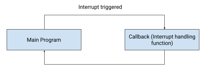
Interrupts are a way for making things happen automatically in your MCU programs. They are a good way of managing time properly. Thanks to them, there's not going to be a need to constantly check the current pin value and instead, whenever a change is detected, an event is triggered.
Everytime an interrupt happens the CPU stops the execution of the main program, goes to execute the task handling the interrupt, and then gets back to the main program:
How to make the connections:
These are the connections you'll need to make for the code in this section to work:
- Pin16 to 330ohm, 330ohm to led, led to pin GND
- Pin17 to 330ohm, 330ohm to led, led to pin GND
- Pin27 to button, button to GND
We want something to happen on a button press. The button press generated signal, looking at the board, looks like this:

We want to enable one led on even count, and the other one on an odd count, and we want to do it as fast as possible. As our button is connecting the input to GND, we'd like to detect the fall of the signal. Consulting the Pin class documentation, we can see that method Pin.irq() offers an option to detect that fall with Pin.IRQ_FALLING, as well as the option of registering a callback function for when the event is detected.
With that in mind, our first code would look like this:
from machine import Pin

# Registering relevant pins
led1 = Pin(16, Pin.OUT)
led2 = Pin(17, Pin.OUT)
p27 = Pin(27, Pin.IN)

# Declaring a global to track the number of callback invocations
count = 0

# Callback to execute upon IRQ triggering
# Receives the pin object where the irq is registered
def setLed(pin):
    global count
    print("Entered handler with count", count)
    if (count % 2) == 0:
        led1.on()
        led2.off()
    else:
        led1.off()
        led2.on()
    count += 1

p27.irq(handler=setLed, trigger=Pin.IRQ_FALLING)
Approach the metal plate of the button without pushing it (a couple of centimeters should do), and see what happens. Why?
The pin is floating! Let's add a pull up resistor in the corresponding pin. Fortunately, we can do that straight from code without the need to wire an external pull up resistor to our button in the breadboard:
from machine import Pin

led1 = Pin(16, Pin.OUT)
led2 = Pin(17, Pin.OUT)
p27 = Pin(27, Pin.IN, Pin.PULL_UP)
count = 0

def setLed(pin):
    global count
    print("Entered handler with count", count)
    if (count % 2) == 0:
        led1.on()
        led2.off()
    else:
        led1.off()
        led2.on()
    count += 1

p27.irq(handler=setLed, trigger=Pin.IRQ_FALLING)
Now, approach the button. Nothing happens, and this is because now the pin is not floating and when we don't push the button, the pin is pulled high (3.3V, or signal 1) thanks to that pull up resistor that we configured in the previous code.
Push the button. If you look closely at the behavior of the LEDs and the output of the callback function, you're kind of gettin an erratic behavior, not the one we were expecting because of each press of the button there's not a single LED switching, which is to say there's not only one call to the handler defined by the trigger function. We see the handler invoked more that once depending on how fast the switch is pushed.
If we were to connect an oscilloscope to the Pin connected to the button, this is what we would see:
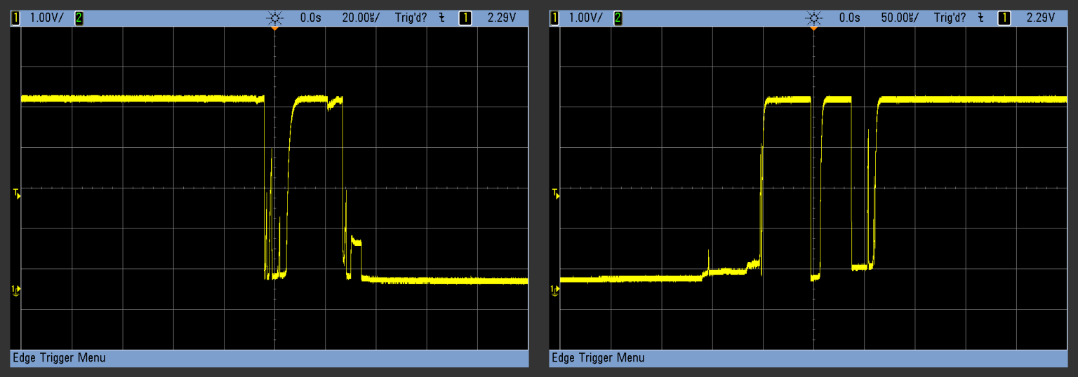
This is not exactly the clear-cut theoretical signal we were taking for granted above when we started designing this experiment. What's happening is that the switch is showing a typical bounce effect.
Info
You can read a lot about debouncing techniques. These techniques can be hardware or software, but in this labs we'll be focusing on software.
We'll focus here on a simple software debouncing technique that consists of:
- Once the callback is called, deactivate the IRQ
- Then, give the signal some time to stabilize so we can be reasonably sure there's not going to be another fall
- Finally, re-enable the irq so we can detect further interruptions
The code would look something like this:
from machine import Pin
import time

led1 = Pin(16, Pin.OUT)
led2 = Pin(17, Pin.OUT)
p27 = Pin(27, Pin.IN, Pin.PULL_UP)
count = 0

def setLed(pin):
    global count
    print("Entered handler with count", count)
    if (count % 2) == 0:
        led1.on()
        led2.off()
    else:
        led1.off()
        led2.on()
    count += 1
    pin.irq(handler=None)
    time.sleep_ms(200)
    pin.irq(handler=setLed)

p27.irq(handler=setLed, trigger=Pin.IRQ_FALLING)
Analog inputs (ADC)
Let's now understand how analog to digital conversion works. This is going to be important if we want to connect to our device the variety of sensors that are out there relying on sending us variations in voltage.
How to make the connections:
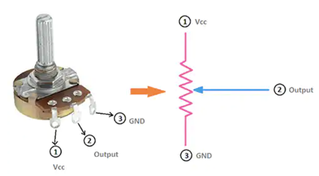
- Place a potentiometer in the board, anyone will do
- Connect pin 1 of the potentiometer to GND
- Connect pin 3 of the potentiometer to 3.3V
- Connect GPIO 32 to the pin 2 of the potentiometer
The working principle of the potentiometer is a simple voltage divider thanks to a variable configuration of resistances:
The voltage divider that the potentiomer is actually configuring is as follows:
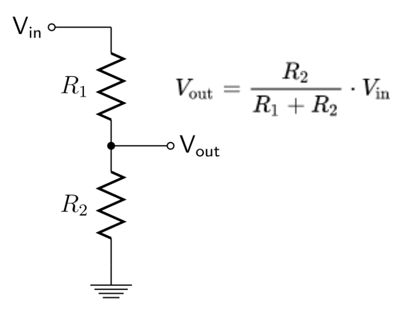
When our potentiometer is turned all the way down, V_out is 0. When our potentiometer is turned all the way up, Vout will be Vin.
Now, let's play with the ADC MicroPython features of the ESP32 thanks to the ADC class:
from machine import Pin, Timer, ADC

pot0 = ADC(Pin(32))
# Set the attenuation to 11dB, giving a maximum input voltage of 3.6v
pot0.atten(ADC.ATTN_11DB)

# Callback printing the pot0 value
def printTime(t):
    print(pot0.read())

# Set a timer to perform measurements on Pin32 periodically
timer1 = Timer(1)
timer1.init(period=200, mode=Timer.PERIODIC, callback=printTime)
Run the program and start moving the potentiometer. You should see variable values ranging from 0 bits to 12 bits (the width of the ADC), or 0 to 4096 in decimal.
Note that we're configuring the ADC with an attenuation of 11DB. According to the documentation, that means that valid input voltage rangest to the pin are in the interval [150mV, 2450mV], so as we're moving our range from [0V,3.3V], expect the ADC lecture to saturate a bit in advance of reaching the max turn of the potentiometer (as from 2450mV to 3300mV our ADC should be giving us the max reading of 4095).
Power management
Power management is a key piece of MCU design and programming, just because most of the devices will run with batteries, that have a limited amount of power that they can provide. Table 8: Power Consumption by Power Modes of the ESP32 Datasheet ou
Running the ESP32 on batteries
If you review the schematics for your ESP32 board (in our case, ESP32 DevKitC1 schematics), you'll see that the EXT_5V is connected to the AMS1117 voltage regulator.
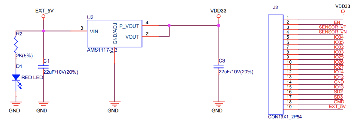
This is coming from USB power in the Dev Board, and the pin is also exposed in the Dev Board in J2 Pin19, marked as EXT_5V. This means that when not getting power from USB, we can supply power to the board through this pin. Because the AMS 1117 voltage regulator is capable of regulating up to 15V (AMS1117 Datasheet), this means that we can connect a 3 AA or AAA battery pack here (summing up a total of 4.5V max) and the regulator will supply to the board the 3.3V that we need.
To test the ESP32 running on batteries, load one of the simple programs that we've tested before in main.py that output a periodic signal to a led, reset the board and check that the program loads and runs properly.
If so, disconnect your Dev Board and proceed to connect a tree AA/AAA battery pack to the board, similar to this one:
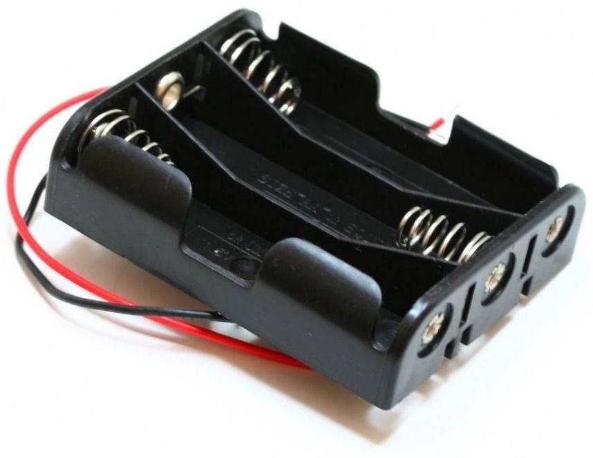
Connect the black cable to the GND pin in the board, and the red cable to the 5V pin in the board. You may need to peel the battery holder cables a bit, or use a pair of alligator cables to connect the battery holder to regular jumper wires that you can connect to the board pins. The Dev Board should light up, meaning that the battery pack is supplying power to the board.
If you have a multimeter at hand, check the voltage between the 3.3V pin and GND pin, and you should see 3.3V being provided to the module. When you're done, disconnect your battery pack.
Sleep and Sleep modes
When running on batteries, running your ESP32 on active mode it’s not ideal, as the power from batteries will drain very quickly.
That's why we'll want to put the ESP32 in sleep mode. This will reduce the power consumption of the board and your batteries will last longer. Depending on the sleep mode the board will stop different components that consume more power, leaving just enough activity to do what we need.
There are three sleep modes supported by the ESP32:
- Light Sleep: . It is used in MicroPython through the
lightsleep()method of themachinepackage. This mode will pause the CPU and will shut down the radio. - Modem Sleep: This mode shuts down the radio while not affecting rest of the components.
- Deep Sleep: This mode will shut down the CPU and the radio, but will leave the RTC (Real Time Clock) and the ULP (Ultra Low Power) coprocessor active.
The detail of each of the modes is outlined in Section 3.7 of the ESP32 Datasheet.
We can send our device to sleep, and then wake it up using three different methods:
- Time wake up
- External interrupt wake up
- Touch pin wake up
Let's practice with different sleep modes and wake up methods.
Light Sleep
Previously, we learned how to use touch detection present in the ESP32 and we mentioned that it can be used to manage sleep modes. This is what we'll do here. Go to the Capacitive touch section and make the connections specified there, and then try the following code in the MicroPython REPL:
import machine
from machine import TouchPad, Pin
import esp32

t = TouchPad(Pin(32))
t.config(500)               # configure the threshold at which the pin is considered touched
esp32.wake_on_touch(True)
machine.lightsleep()        # put the MCU to sleep until a touchpad is touched
This test is more educative if you have the ESP32 connected through WiFi and you check that during light sleep, you lose WiFi connectivity.
Deep Sleep
In deep sleep mode the ESP32 have a current consumption on the μA range. Getting power consumption under control means doing a careful hardware design so your board you can get a minimal comsumption. Here we're using a full-feature ESP32 development board with built-in programmer, on-board sensor, etc., and we won’t be able to get the minimum possible power consumptions for a given application, but still we can reduce it and learn in the process.
Let's try it together with a couple of methods to wake the device from deep sleep.
Time wake up
Let's put the device to sleep and wake it up after certain time has passed. For this test, we'll need the following components connected to the breadboard:
- Pin 18 to one end of a 330Ohm resistor
- The other end of the 330Ohm resistor to the positive terminal of a LED
- Negative terminal of the LED to GND
Open a MicroPython REPL and write the following code:
from machine import Pin, deepsleep

led0 = Pin(18, Pin.OUT, value=1)

# Sleep time in ms
deepsleep(10000)
You should see that the led goes on and once you execute the deepsleep(10000) line the device goes off and resets itself after 10 seconds, giving you back the MicroPython REPL.
Info
Because the ESP32 is a 32-bit microcontroller, the maximum time for every sleep mode is the maximum value for a 32-bit unsigned integer. That is 0xFFFF FFFF or 4294967295 microseconds, or 71 minutes.
External interrupt wakeup
Now, let's configure an external interrupt wake up signal. For this, we'll use the esp32 MicroPython module, that contains the methods wake_on_ext0() and wake_on_ext1() that configures the device to wake up on external interrupts. The methods can be associated to any input pin, in our case that contains a pull down resistor as we're going to use a button to send a True (high) to make the wake up call. So, as the wake up signal will be on a high, we'll use esp32.WAKEUP_ANY_HIGH as value for level inside the method.
To test this, you'll need the following connections:
- Pin 18 to one end of a 330Ohm resistor
- The other end of the 330Oh to the positive termina of a LED
- Negative terminal of the LED to GND
- Pin 14 to one end of a push button
- The other end of the push button to GND
First, we'll need to load the following program into main.py:
import machine, esp32, sys
from machine import Pin
from time import sleep

# Set pin for signaling when the device is awake
led0 = Pin(18, Pin.OUT, value=1)

# Check if the device woke up from a deep sleep
if machine.reset_cause() == machine.DEEPSLEEP_RESET:
    print("Woke up from deep sleep")
    sys.exit()

# Set Pin 14 as wake up signal source
rst0 = Pin(14, Pin.IN, Pin.PULL_DOWN)
esp32.wake_on_ext0(pin = rst0, level = esp32.WAKEUP_ANY_HIGH)

# Keep the MCU active for active_time
active_time = 10
print("Active for 10 seconds")
sleep(active_time)
print("Going to Deep Sleep, use button to wake up")
machine.deepsleep()
If you push the EN button of your board, you will see the ligh on for active_time seconds, and the led will go off indicating that the device is in deep sleep. If you then push the button, you'll see that the device wakes up and the led turns on again.
Measuring deep sleep power consumption
We'll take advantage of this code to actually measure the power consumption by measuring the current supplied by a battery pack when the device is active, and when it's in deep sleep.
To test it, we'll need to make the following connections:
- Pin 18 to one end of a 330Ohm resistor
- The other end of the 330Oh to the positive termina of a LED
- Negative terminal of the LED to GND
- Negative cable of the battery pack to GND
- Positive cable of the battery pack to positive probe of a multimeter
- Negative probe of the multimeter ready (but not yet connected) to be connected to
EXT_5Vpin in the board
For the last two connections, you may use a combination of alligator clips and jumper wires to make them physically possible. Do not forget to connect the multimeter probes to the right terminals in your multimeter. You're going to read microAmps, so be mindful of that when setting it up.
Now disconnect the ESP32 from USB power. You'll lose connectivity to the board, but it does not matter as we've got visibility on the sleep state of the device thanks to the external LED. Now connect the positive terminal of the multimeter to the EXT_5V pin of the device. You should see both the internal power LED and the external LED you connected ligth up. The multimeter should read the current draw of the ESP32 in active mode. Depending on if you're using radio or not, you should get a measurement ranging between 40mA and 250mA.
Wait 10 seconds for the deep sleep mode to trigger, and you should see a sudden drop in drawn current from the battery pack. This, as well as the external LED going off, signals the ES32 entering deep sleep mode. The current draw should now be around 10 mA.
Info
Espressif claims much lower power consumptions in deep sleep mode. This is for the ESP32 module, and we're using here a Dev Board with additional components. The power consumption will then be impacted by the Dev Board design, so different boards will show different consumption patterns.